
Call:
 Send Inquiry
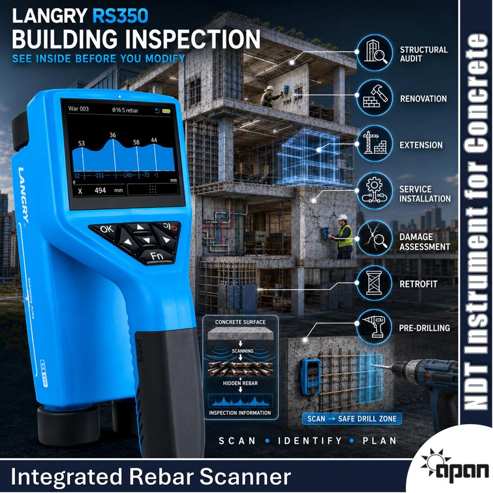
The LANGRY RS350 Integrated Rebar Scanner is an advanced non-destructive testing instrument designed for the detection and analysis of reinforcement bars embedded inside reinforced concrete structures. It enables professionals to identify rebar position, distribution, direction, concrete cover thickness, and estimated rebar diameter without damaging the concrete surface.
Designed for modern construction inspection, structural assessment, renovation, retrofitting, infrastructure maintenance, and engineering diagnostics, the RS350 combines a high-precision sensing system, multiple scanning modes, high-resolution display, four-line laser positioning, wireless connectivity, data management, 3D visualization, and professional reporting software in one integrated solution.
Reinforced concrete may appear solid and uniform from the outside, but its internal reinforcement arrangement is critical to structural performance. Before drilling, coring, cutting, anchoring, retrofitting, or carrying out structural modifications, engineers often need reliable information about what lies beneath the concrete surface.
The LANGRY RS350 Rebar Scanner provides a practical non-destructive method for obtaining this information.
With a maximum published scanning range of up to 210 mm, an applicable rebar diameter/cover measurement range of 650 mm, estimated diameter display precision of 0.1 mm, and multiple scanning modes, the RS350 is designed to support both rapid field investigations and more detailed reinforcement mapping.
Reinforcement bars are hidden beneath the concrete surface. Once a structure has been completed, the exact reinforcement arrangement may not always be visible or accurately documented.
Construction drawings can provide valuable information, but actual reinforcement may differ from original drawings because of construction modifications, field conditions, undocumented repairs, or changes made during the life of the structure. This creates a major challenge for engineers. Before drilling a hole into a concrete slab, installing an anchor, cutting a wall, creating an opening, carrying out a core sample, or modifying a structural element, it is important to understand the location of embedded reinforcement.
Uncontrolled drilling or cutting can damage reinforcement and potentially compromise structural performance.
A professional concrete rebar scanner provides a non-destructive way to investigate reinforcement before intervention.
The LANGRY RS350 can assist professionals in identifying:
This makes the RS350 a valuable tool for construction quality control, structural inspection, renovation, maintenance, retrofitting, and infrastructure assessment.
The RS350 is designed as an integrated rebar scanning platform rather than simply a basic rebar locator.
Its purpose is to transform underground reinforcement information into useful engineering data.
The instrument combines:
High-precision sensing Rebar detection Cover measurement Diameter estimation Position identification Data recording Visualization Analysis Reporting
This workflow can significantly improve the efficiency of concrete reinforcement investigations.
The RS350 supports multiple scanning modes, including Quick Scan, Procedural Scan, Grid and Image, Wave Scan, Fine Scan, and complex-working-condition detection modes. The system also supports USB/Bluetooth data transfer and professional software for 3D modelling, intelligent analysis, and automatic report generation.
The RS350 incorporates a high-precision sensor designed to improve reinforcement detection and measurement performance.
The instrument is intended to detect embedded reinforcement and provide information about its position and characteristics without destructive excavation.
This makes it suitable for applications where preserving the concrete surface is important.
The published specification provides two measurement ranges:
First range: 1120 mm
Second range: 1210 mm
The applicable range for protective-layer thickness and estimated rebar diameter is specified as 650 mm.
Actual performance can vary according to reinforcement spacing, concrete properties, surrounding materials, environmental conditions, and other site factors, so measurements should always be interpreted according to the manufacturers operating guidance.
Concrete cover is an important parameter in reinforced concrete construction. The concrete layer between the surface and the reinforcement helps protect the steel reinforcement from environmental exposure and contributes to the structure's durability.
Insufficient or inconsistent cover can be an important consideration during structural inspection and durability assessment.
The RS350 is designed to detect reinforcement and determine the thickness of the concrete cover above the detected rebar.
The published performance data gives different allowable deviations depending on measurement depth:
|
Cover Depth |
Maximum Allowable Error |
|
180 mm |
1 mm |
|
81120 mm |
2 mm |
|
121160 mm |
3 mm |
|
161210 mm |
4 mm |
These values apply to the specified testing conditions and should not be treated as a universal accuracy guarantee for every field condition.
The RS350 is designed not only to locate reinforcement but also to estimate the diameter of embedded reinforcement.
The published applicable diameter estimation range is 650 mm, with a maximum estimated-diameter error of 1 specification under optimal conditions. The displayed diameter precision is 0.1 mm.
Diameter estimation can provide valuable supplementary information during structural investigations.
For example, engineers may use measured reinforcement information to compare field conditions against:
The scanner therefore becomes more than a simple locating device; it can support a broader structural investigation workflow.
Different concrete structures present different inspection challenges.
A simple surface scan may be sufficient for one application, while a complex reinforced concrete element may require more detailed imaging and analysis.
The RS350 supports multiple scanning modes, including:
Designed for rapid identification of reinforcement.
This mode can be useful when engineers need to quickly determine the approximate position of reinforcement before performing another activity.
Designed for structured scanning and data collection.
It can help organize inspection work when systematic scanning is required.
Grid-based scanning can provide a more visual representation of reinforcement distribution.
This can be particularly useful for slabs, walls, decks, and other relatively large concrete surfaces.
Wave-based scanning provides another visualization approach for interpreting detected reinforcement.
Fine scanning can be used when more detailed examination is required.
The RS350 is also designed to support detection under more challenging conditions, including specialized modes for rebar avoidance, concave surfaces, and convex surfaces.
This range of scanning options makes the instrument suitable for different structural geometries and inspection requirements.
One of the challenges in concrete scanning is the presence of closely spaced or dense reinforcement.
When multiple rebars are positioned close together, identifying individual bars and accurately determining cover thickness can become more challenging.
The RS350 incorporates an optimized rebar judgment algorithm designed to improve recognition of dense reinforcement under different scanning modes. This optimization is intended to improve recognition capability and provide more accurate protective-layer thickness values.
This feature can be particularly valuable when inspecting:
Accurate positioning is an important part of professional reinforcement scanning.
The RS350 incorporates an upgraded four-line laser positioning system.
The system provides real-time display of rebar positions and centerlines of adjacent reinforcement and incorporates positioning aids such as an aiming frame and indicator lights.
This can help engineers identify the position of reinforcement more clearly on the concrete surface.
Laser positioning can also be useful during:
Instead of simply knowing that reinforcement exists somewhere below the surface, the operator can use the positioning system to better identify the detected rebar location.
Modern NDT instruments need to do more than display readings.
Inspection data increasingly needs to be transferred, stored, analyzed, shared, and incorporated into project documentation.
The RS350 supports wireless connection with mobile phones and can enable real-time online testing and uploading of testing data to cloud platforms.
The published specifications also identify Bluetooth and USB as data transmission options.
This connectivity can simplify the workflow from field inspection to engineering documentation.
One of the strongest advantages of an integrated rebar scanner is the ability to move beyond individual measurements.
Professional computer software supports:
Data storage capacity of more than 5,000 measurements/data items and support for USB or Bluetooth data transfer.
This creates a more complete digital inspection workflow:
FIELD SCAN DATA STORAGE DATA TRANSFER 3D VISUALIZATION ANALYSIS REPORT
For engineering consultants and NDT service providers, this can be particularly useful because inspection results often need to be documented and presented to clients.
Understanding reinforcement becomes easier when complex information is represented visually.
The RS350s software supports 3D model generation, allowing reinforcement information to be represented graphically.
A 3D visualization can help engineers understand:
This can be valuable for project documentation and structural assessment.
|
Product Type |
Integrated Rebar Scanner |
|
Primary Application |
Reinforced Concrete Inspection |
|
First Measurement Range |
1120 mm |
|
Second Measurement Range |
1210 mm |
|
Applicable Rebar Diameter Range |
650 mm |
|
Applicable Diameter Estimation Range |
650 mm |
|
Maximum Estimated Diameter Error |
1 specification |
|
Diameter Display Precision |
0.1 mm |
|
Scanning Modes |
Quick / Procedural / Grid & Image / Wave / Fine |
|
Complex Condition Detection |
Supported |
|
3D Imaging |
Supported |
|
Data Transfer |
USB / Bluetooth |
|
Wireless Connectivity |
Supported |
|
Data Storage |
More than 5,000 |
|
Laser Positioning |
Four-line |
|
Screen |
3.5-inch color touchscreen |
|
Screen Resolution |
640 480 |
|
Host Weight |
Approximately 650 g |
|
Host Dimensions |
Approximately 210 95 120 mm |
|
Battery |
Plug-in lithium battery |
|
Battery Life |
Up to approximately 24 hours* |
|
Charging Time |
Approximately 6 hours* |

Price:
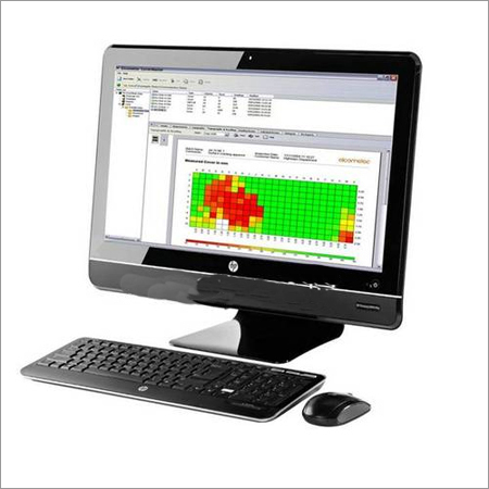
Control Mode : Digital Control
Machine Weight : 25 kg
Accuracy : 0.5%
Power Supply : AC 220V / 50Hz
Measuring Range : Wide
Response Time : <1s
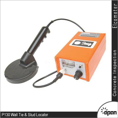
Control Mode : Automatic / Manual
Machine Weight : Approx. 150 g
Accuracy : 1 mm
Power Supply : 9V Battery
Measuring Range : 038 mm
Response Time : <1 second

Control Mode : Manual
Machine Weight : 350 g (approx.)
Accuracy : 1 mm (when used with recommended cover meter)
Power Supply : Not Required (Accessory Item)
Measuring Range : Dependent on instrument, generally up to 100 mm
Response Time : Immediate
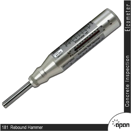
Control Mode : Manual
Machine Weight : 1.1 kg
Accuracy : 1 N/mm
Power Supply : Not Required (Manual Operated)
Measuring Range : 10 70 MPa
Response Time : Instantaneous
GST : 24AKYPB1970A1ZE


 Send Inquiry

 Send Inquiry


